
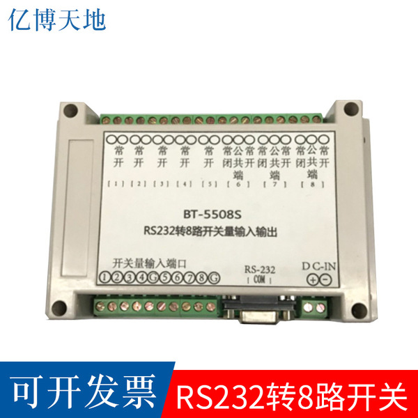
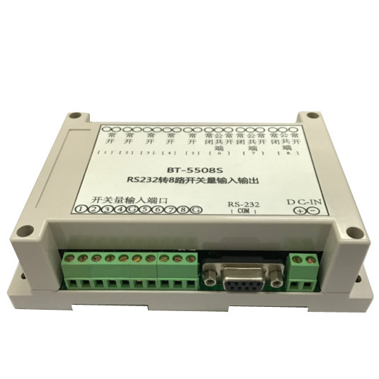
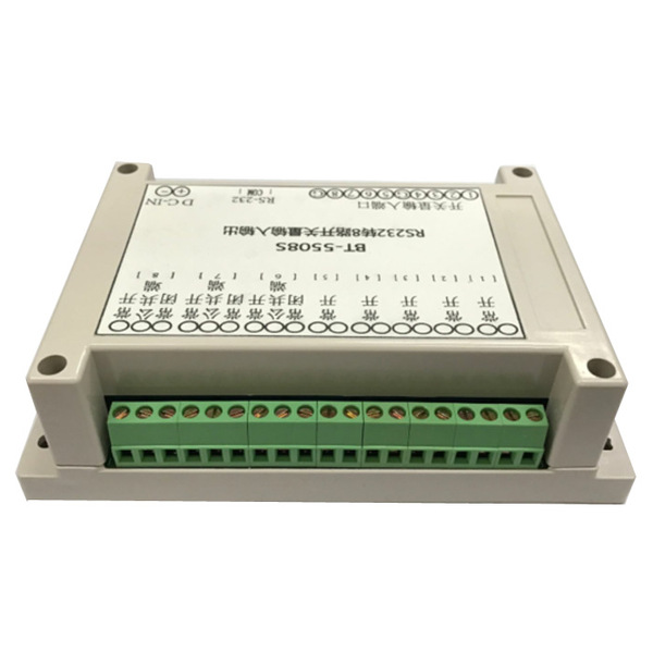
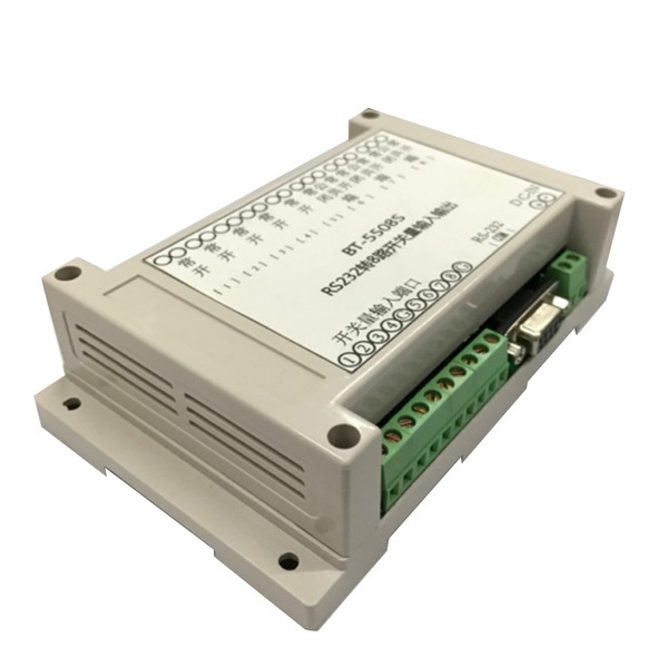
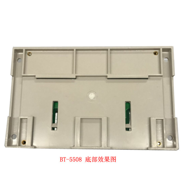


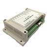
Product: RS232 to 8-way switch value


The download address of the upper machine test software and instructions:https://pan.baidu.com/s/1GFF1PAF provides test software and upper machine development data SDK!
Input and output of switchingsayMingBook
1. Main performance profile
The input and output module of the switch can be widely used in various industrial measurement and control systems.The main computers, the main controller and other upper machines through RS-232, RS-485, or USB interface can control the module to collect the input switch amount, and output the corresponding switching signalWait; the upper machine can query the input and output state of the module at any time.The module adopts a standard MODBUS communication protocol that is convenient for the control module as other manufacturers to hang on the same bus, and it is convenient for computer programming.Its functions and technical indicators are as follows:
1. Input of switching: 4 or 8 input, compared to short -circuit or opening of the public end.
2. Switching output: 4 or 8 output, relay contact output form (including often closed end, public end, often start).
3. Communication interface:
(1) RS-485 interface, second-line system, 15KV ESD protection.
(2) RS-232 interface, three-line system, 15kV ESD protection.
(3) USB serial port, USB2.0 interface.
4. Communication protocol: MODBUS RTU protocol.
5. Communication rate: 2400 ~ 115200bps, which can be set up by dial -switch and the upper machine software.
6. serial port settings: 8 data bit, 1 stop bit, no verification.
7. Module Address: 1 to 247, which can be set up by dial -dial -switch, and can be set by the upper machine software.
8. Power input: DC 9 ~ 100V.
9. Working environment:
The working temperature is -30 ℃ ~ 70 ℃; the storage temperature is -40 ℃ ~ 85 ℃; the relative humidity is -5%to 95%does not expose.
Warning: The upper machine communication interface device should be a standard product that meets the corresponding specifications. It is not possible to use cheap and simple devices (signal electrical features do not comply with relevant protocol specifications), otherwise communication data errors or irreversible damage to module communication interfaces will be caused.
10. Products provide supporting upper machine test software for test debugging and use

(1) Power input
The module is powered by DC power, and the power consumption is about 0.5W to 1.5W.Because the module uses high-quality power chips, it supports ultra-width temperature (-20 ° C ~ 85 ° C), ultra-wide voltage (9V ~ 100V) application, the conversion efficiency is as high as 98%, and the heat is extremely small.
(2) Input of switching quantity
The module can be connected to the input signal 4 or 8.The input interface of the switching volume adopts a dry connection point, and the input channel has been pulled up to the high level. The short or low -electric input with the GND or the input of the GND is usually effective input. It is invalid or input to hang it or input high -electricity.The high -level input range is 3.3V to 24V.
When the input channel is valid, the LED light is turned on corresponding to the wiring terminal, otherwise, the LED light is extinguished.
(3) Switch output
The module can connect the output signal of 4 or 8 switching, and the output of the switching volume is the contact of the continuation.When the output channel is invalid, the relay has no control signal, the contacts are often open, and the constant closed contacts are closed; when the output channel is valid, the relay has a control signal, the contacts are closed, and the constant closed contact is broken.
When the output channel is valid, the output LED light is on next to the wiring terminal.Conversely, LED lights go out.
(3) communication interface
The communication interface of the RS-232 is in the form of DB9 mother seat, and each pin is defined as the following table.
Table 1 DB9 parent seat communication interface pin definition
Point 5 4 3 2 1
Define GND RS-232 to receive RS-232 sending
The USB serial port uses CH340 chip to convert the serial port TTL level to a USB signal. When using this interface, the upper machine needs to install the CH340 serial chip driver.
When the RS-485 signal connection bus, the A-end connection of all modules, the B-end connection of the B-side and all modules, and the proximal and remote connection resistance on the RS-485 bus (this module has built-inMatch the resistance, choose the access through the jumper J4).
(4) Dial switch description
There are 8 bits of dialing switches, and the first 5 bits are used to set the address of the module, which is marked as A0 to A4; the latter 3 bits are used to set the module's baud rate, which is marked as B0 to B2.The setting value of the dial -dial switch is 2nd -in, and the corresponding setting value of each dial to on ON is 0, and the corresponding setting value when dial to OFF is 1.
Figure 3 Dial -dial switch
When A0 to A4 is all set to 1 (OFF), the module's mailing address is set by the software.The upper machine sets the mailing address range of the module through the MODBUS protocol, and the module is automatically reset after setting, and runs according to the new setting value.
When A0 to A4 is set to 0 (on), the module's mailing address is determined by dial.The address address of the module is set in the table below by dialing the module, and the dial bits are added from high to low as the address setting value.After setting, you need to restart the module manually and run according to the new setting value.
Table 2 Dial -setting module mailing address
A4 A3 A2 A1 A0 Address
0 0 0 0 1 1
0 0 0 1 0 2
0 0 0 1 1 3
0 0 1 0 0 4
... ...
1 1 1 0 1 29
1 1 1 1 0 30
1 1 1 1 1 Software setting
When B0 to B2 is all set to 1 (OFF), the module's communication baud rate is set by software.The Potter rate range of the upper machine through the MODBUS protocol is 2400 to 512000bps. After setting, the module automatically resets and run according to the new settings value.
2. Example
(1) Function code 01 (0x01): Read 1 or multi -road switch output state Do DO
Starting position: 0 to 7; the number of switches: 1 to 8; the command of the scope is invalid
The number of starting positions + switching amount: 1 ~ 8; exceeding the scope command is invalid
Example: The output status of the host to read the address is 01, the switch volume do1 ~ DO4
Host sending: 01 01 0000 0004 CRC [01 01 00 00 00 04 3D C9] Read 4th Road do
Address function code Start position read switch to measure the number CRC code
From machine response: 01 01 01 Data CRC [01 01 01 00 51 88] Back 4 -way do are invalid
Address function code data length DO4 ~ DO1 CRC code (D7-D4 invalidation 0)
(2) Function code 02 (0x02): Read 1 or multi -way switch input state di
Starting position: 0 to 7; the number of switches: 1 to 8; the command of the scope is invalid
The number of starting positions + switching amount: 1 ~ 8; exceeding the scope command is invalid
Example: The host must read the address 01, the input status of the switch volume DI1 ~ DI4
Host sending: 01 02 0000 0004 CRC [01 02 00 00 00 00 04 79 C9] Read 4 DI
Address function code Start position read switch to measure the number CRC code
From machine response: 01 02 01 Data CRC [01 02 01 00 A1 88] Returning 4 -way DI is invalid
The length of the address function code data DI4 ~ DI1 CRC code (D7-D4 invalidation 0)
(3) Function code 03 (0x03): Read the retaining register (read module address, baud rate (2 registers))
Starting position: 0 ~ 2; Number of registers: 1 ~ 3; exceeding the scope command invalid
Number of starting position + register: 1 ~ 3; exceeding the range command invalid
Example: The host reads the module address and baud rate
Sales of the host: 01 03 0000 0003 CRC [01 03 00 00 00 00 03 05 CB]
Address function code Start position read register number CRC code
From machine response: 01 03 06 add_h add_l BDRT3 BDRT2 BDRT1 BDRT0 CRC
Address Function Code by bytes Addressing High bytes Low Way High byte High byte ...
If the data add_h add_L is 0001, it means that the module address is 01H
For example, data BDRT3 BDRT2 BDRT1 BDRT0 is 0001C200, indicating that the baud rate is 115200
(4) Function code 05 (0x05): Write the output state
The control command is: "FF00" is the output switch volume to "1", that is, control the relay "combined"; "0000" is the output switch volume to "0", that is, the control relay "divide".
Example: The host must control the address 01, and the first line is switched to DO1 (or relay) "combined". The host sends:
01 05 0000 FF00 CRC [01 05 00 00 FF 00 8C 3A] Write the 1st DO combination (valid)
Address function code Start position Write switch to measure the CRC code
From machine response: 01 05 0000 FF00 CRC [01 05 00 00 FF 00 8C 3A]
Address function code Start position Write switch to measure the CRC code
Example: The host should control the address 01, and the first pass to the DO1 (or relay) "divide" host:
01 05 0000 0000 CRC [01 05 00 00 00 00 CD CA] Write the first DO DO (invalid)
Address function code Start position Write switch to measure the CRC code
From machine response: 01 05 0000 0000 CRC [01 05 00 00 00 00 CD CA]
Address function code Start position Write switch to measure the CRC code
(5) Function code 06 (0x06): Write a single retaining register (module address, baud rate (2 registers))
Starting position: 0 to 7; Number of registers: 1 ~ 8; Walking or not effective
Number of starting positions + registers: 1 ~ 8; invalidation of the scope command
Example: The host should control the address 01 and write the module address.
Host sending: 01 06 0000 0001 CRC [01 06 00 00 00 00 01 48 0A] Writing module address
Address function code Start position module address CRC code
From machine response: 01 06 0000 0001 CRC [01 06 00 00 00 01 48 0A]
Address function code Start position module address CRC code
(6) Function code 0F (0x0F): Write multi -circuit switch output state do do
Starting position: 0 to 7; the number of switches: 1 to 8; the command of the scope is invalid
The number of starting positions + switching amount: 1 ~ 8; exceeding the scope command is invalid
Example: The host needs to read the address of 01, the output status of the switch volume do1 ~ DO4, the host sends:
01 0F 0000 0004 01 Data CRC [01 0F 00 00 00 00 04 01 0F 7E 92]
Address function code Start position output quantity byte count DO4 ~ DO1 CRC code (D7-D4 invalid complement 0)
From machine response: 01 0F 0000 0004 CRC [01 0F 00 00 00 00 04 54 08]
Address function code Start position output quantity CRC code
(7) Function code 10 (0x10): Write multiple maintenance registers (module address, baud rate (2 registers))
Starting position: 0 ~ 2; Number of registers: 1 ~ 3; exceeding the scope command invalid
Number of starting position + register: 1 ~ 3; exceeding the range command invalid
Example: The host writes the module address and baud rate, the host sends:
01 1000 0003 06 add_h add_L BDRT3 BDRT2 BDRT1 BDRT0 CRC
Address Function Code Starting position Verseter Digital bytes Addressing High -word Portal Port Rate High Words ... Potal Rate low -character CRC code
From machine response: 01 100000 0003 CRC
Address function code Start position register single number CRC code
(8) Function code (0x11): Report ID from the machine
Host sends: 01 11 00 00 00 00 CRC [01 11 00 00 00 00 00 80 C6]
The address function code arbitrarily 1 ... any number 6 CRC code
From machine response: 01 11 71 FF 04 04 00 00 CRC
Address function code byte 1 byte 2 bytes, 4 bytes, 5 bytes 6 CRC code
From the machine ID contains 6 bytes, byte 1: Device ID (0x71), byte 2: Running Sign (0xff), byte 3: Switching volume Input channel quantity, byte 4: number of switch quantity output channels, words, words, wordsSection 5: Number of simulation input channels, byte 6: Simulation output channel quantity.